


Der Schaltplan zeigt schematisch die Komponenten der elektrischen Anlage, die Funktionen und die Stromverläufe an.
In der Betriebsanleitung, die jedem Fahrzeug einst beilag, ist der Schaltplan im Format A5 abgedruckt, aber wegen dem Massstab und der einfarbigen Unterlegung nur schwer lesbar. Im Werkstatt-Handbuch ist der Schaltplan besser lesbar, da er dem Format A4 angepasst ist.
In der Tabelle ist angeführt in welchem Werkstatt-Handbuch die Schaltpläne abgedruckt sind.
Für die Modelljahre 1961 bis 1969 gibt es nur vier unterschiedliche Schaltpläne. Der Sicherungskasten enthält nur drei Schmelzsicherungen mit je 35 Ampere.
Bei den Modellen mit der D-Jetronic werden die einzelnen Komponenten durch 12 Schmelzsicherungen in unterschiedlicher Nennstromstärke gesichert.
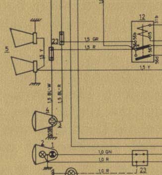
Schaltplan in der Betriebsanleitung (Ausschnitt)
Colour Wiring Diagrams | Warren Townsend
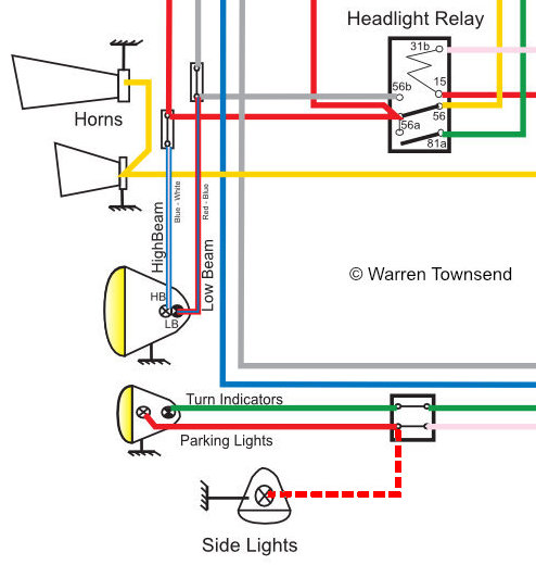
Artwork by Warren Townsend - 2019 - Melbourne Australia - Available for free use in the classic Volvo community
Based on an original Swedish Design Concept of the 1960s and 70s.
I have attempted to make these Wiring Diagrams as accurate as possible, however no responsibility is accepted for any consequential errors from their use. In some instances Volvo made mid run production changes, please also reference previous, or subsequent year's schematic.
The PDF files can be printed in any format or as a cut-out.
Warren Townsend, thank you very much!
[www.volvo1800-120club.com]
| Colour Wiring Diagrams - © Warren Townsend | ||||||
| No. 1 | P1800 | 1-6.000 | 1961-1963; VA/HA | P1800 1961-1963 | V 3.1 Oct 2025 | |
| No. 2 | 1800S | 6.001-8.000 | 1963; VB/HB | 1800S 1963 | V 3.1 Oct 2025 | |
| No. 3 | 1800S | 8.001-12.499 | 1964; VD/HD | 1800S 1964 | V 3.1 Oct 2025 | |
| No. 4 | 1800S | 12.500-28.300 | 1965-1968; E ,F, M, P | 1800S 1965-1968 | V 3.0 Dec 2023 | |
| No. 5 | 1800S | 28.301-29.993 | 1969; S | 1800S 1969 | V 3.0 Dec 2023 | |
| No. 6 | 1800E | 30.001-32.799 | 1970; T | 1800E 1970 | V 3.5 Aug 2025 | |
| No. 7 | 1800E | 32.800-37.549 | 1971; U | 1800E 1971 | V 3.5 Aug 2025 | |
| No. 8 | 1800E | 37.550-39.414 | 1972; W | 1800E 1972 | V 3.6 Nov 2025 | |
| No. 9 | 1800ES | 0001-3.069 | 1972; W | 1800ES 1972 | V 3.6 Nov 2025 | |
| No. 10 | 1800ES | 3.070-8.078 | 1973; Y | 1800ES 1973 | V 3.7 Nov 2025 | |
Elektrische Schaltpläne | Werkstatt-Handbuch
| Electrical circuit diagrams - Workshop manual black/white | ||||||
| Modell | ch # | Modelljahr | Plan # | Quelle | ||
| No. 1 | P1800, P1800S | 1-7.000 | 1961; A, B | 101632 | 1, 2 | |
| No. 2 | P1800S, 1800S | 7.001-10.000 | B, D | 101630 | 1, 2 | |
| No. 3 | 1800S | 10.001-12.500 | 1964; D | 101629 | 1, 2 | |
| No. 4 | 1800S | 12.501-30.000 | 1965; E, F, M, P, S | 101631 | 1, 2 | |
| No. 5 | 1800E | 30.001-32.799 | 1970; T | 104457 | 2 | |
| No. 6 | 1800E | 32.800-37.549 | 1971; U | 105727 | 2 | |
| No. 7 | 1800E | 37.550-39.414 | 1972; W | 106624 | 2; 3 | |
| No. 8 | 1800ES | 1-3.069 | 1972; W | 106625 | 2, 4 | |
| No. 9 | 1800ES | 3.070-8.077 | 1973; Y | 107472 | 2 | |
Quellen
1 Werkstatt-Handbuch 3 Elektrische Anlage 1800; TP 10335/1; 1967
2 Verkstads Handböcker 3 Elektriskt system 1800; TP 1033/2; 1975
3 Werkstatt-Handbuch 1800E Vorläufige Ausgabe; TP 10581/1
4 Werkstatt-Handbuch Volvo 1800 E, 1800 ES Technische Neuheiten 1972; TP 10746/1
