


Der Schaltplan zeigt schematisch die Komponenten der elektrischen Anlage, die Funktionen und die Stromverläufe an.
In der Betriebsanleitung, die jedem Fahrzeug einst beilag, ist der Schaltplan im Format A5 abgedruckt, aber wegen dem Massstab und der einfarbigen Unterlegung nur schwer lesbar. Im Werkstatt-Handbuch ist der Schaltplan besser lesbar, da er dem Format A4 angepasst ist.
In der Tabelle ist angeführt in welchem Werkstatt-Handbuch die Schaltpläne abgedruckt sind.
Für die Modelljahre 1961 bis 1969 gibt es nur vier unterschiedliche Schaltpläne. Der Sicherungskasten enthält nur drei Schmelzsicherungen mit je 35 Ampere.
Bei den Modellen mit der D-Jetronic werden die einzelnen Komponenten durch 12 Schmelzsicherungen in unterschiedlicher Nennstromstärke gesichert.
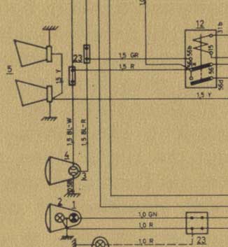
Kopplingsschema i bruksanvisningen (detalj)
Elektriska kopplingsscheman i färg | Warren Townsend
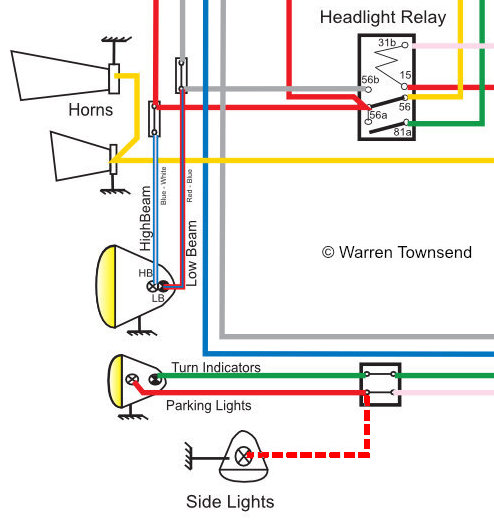
Dessa kopplingsscheman har producerats i färg av Warren Townsend, Melbourne (AU) från ett svenskt designkoncept. Han har vänligen gjort dem tillgängliga för Volvokollektivet i PDF-format och tillhandahåller dessa anvisningar:
Jag har försökt att göra dessa kopplingsscheman så korrekta som möjligt, men tar inget ansvar för eventuella följdfel som uppstår vid användning av dem.
I vissa fall har Volvo gjort ändringar i mitten av modellåret, se därför även kopplingsscheman för föregående eller efterföljande år.
PDF-filerna kan skrivas ut i vilket format som helst eller som utklipp.
Warren Townsend, thank you very much!
[www.volvo1800-120club.com]
| Colour Wiring Diagrams - © Warren Townsend | ||||||
| Modell | ch # | Year |  |
Version / Date | ||
| No. 1 | P1800 | 1-6.000 | 1961-1963; VA/HA | P1800 1961-1963 | V 3.1 Oct 2025 | |
| No. 2 | 1800S | 6.001-8.000 | 1963; VB/HB | 1800S 1963 | V 3.1 Oct 2025 | |
| No. 3 | 1800S | 8.001-12.499 | 1964; VD/HD | 1800S 1964 | V 3.1 Oct 2025 | |
| No. 4 | 1800S | 12.500-28.300 | 1965-1968; E ,F, M, P | 1800S 1965-1968 | V 3.0 Dec 2023 | |
| No. 5 | 1800S | 28.301-29.993 | 1969; S | 1800S 1969 | V 3.0 Dec 2023 | |
| No. 6 | 1800E | 30.001-32.799 | 1970; T | 1800E 1970 | V 3.5 Aug 2025 | |
| No. 7 | 1800E | 32.800-37.549 | 1971; U | 1800E 1971 | V 3.5 Aug 2025 | |
| No. 8 | 1800E | 37.550-39.414 | 1972; W | 1800E 1972 | V 3.5 Aug 2025 | |
| No. 9 | 1800ES | 0001-3.069 | 1972; W | 1800ES 1972 | V 3.5 Aug 2025 | |
| No. 10 | 1800ES | 3.070-8.078 | 1973; Y | 1800ES 1973 | V 3.6 Aug 2025 | |
Elektrische Schaltpläne | Werkstatt-Handbuch
| Elektrische Schaltpläne - Werkstatt-Handbuch schwarz/weiss | ||||||
| Modell | ch # | Modelljahr | Plan # | Quelle | ||
| No. 1 | P1800, P1800S | 1-7.000 | 1961; A, B | 101632 | 1, 2 | |
| No. 2 | P1800S, 1800S | 7.001-10.000 | B, D | 101630 | 1, 2 | |
| No. 3 | 1800S | 10.001-12.500 | 1964; D | 101629 | 1, 2 | |
| No. 4 | 1800S | 12.501-30.000 | 1965; E, F, M, P, S | 101631 | 1, 2 | |
| No. 5 | 1800E | 30.001-32.799 | 1970; T | 104457 | 2 | |
| No. 6 | 1800E | 32.800-37.549 | 1971; U | 105727 | 2 | |
| No. 7 | 1800E | 37.550-39.414 | 1972; W | 106624 | 2; 3 | |
| No. 8 | 1800ES | 1-3.069 | 1972; W | 106625 | 2, 4 | |
| No. 9 | 1800ES | 3.070-8.077 | 1973; Y | 107472 | 2 | |
Quellen
1 Werkstatt-Handbuch 3 Elektrische Anlage 1800; TP 10335/1; 1967
2 Verkstads Handböcker 3 Elektriskt system 1800; TP 1033/2; 1975
3 Werkstatt-Handbuch 1800E Vorläufige Ausgabe; TP 10581/1
4 Werkstatt-Handbuch Volvo 1800 E, 1800 ES Technische Neuheiten 1972; TP 10746/1
